✕
Last month’s article on CO2 introduced readers to the properties of this low-GWP refrigerant, which has been around for a very long time and can keep food cold without harming the environment. There was also a discussion about some of the modifications that are needed when working with this high-pressure gas.
This article is directed at those who are teaching students and technicians about CO2 and other refrigerants. It will help connect what students already know about the properties of HFC and HFO refrigerants with CO2 as a refrigerant. HFC and HFO blends have very high GWPs, while CO2 has a GWP of 1. And yet, many similarities exist between these gases.
Step One: Compare Systems
When teaching students about CO2, the first step should be to compare the basic refrigeration cycle with the CO2 system. With their much higher pressures, CO2 systems may seem daunting to students, which is why every effort must be made to explain the similarities between the two systems.
First, cover the basic refrigeration cycle using HFC/HFO refrigerants and the associated high- and low-side pressures that cause change of state. Then, walk students through the entire cycle for a CO2 system, comparing the pressures in each system type. Explain what must be done to provide a sealed environment that produces sufficient liquid to do the work of removing heat from a conditioned space so it can be rejected into the outdoor ambient or reclaimed in some way to heat water or be used for another purpose.
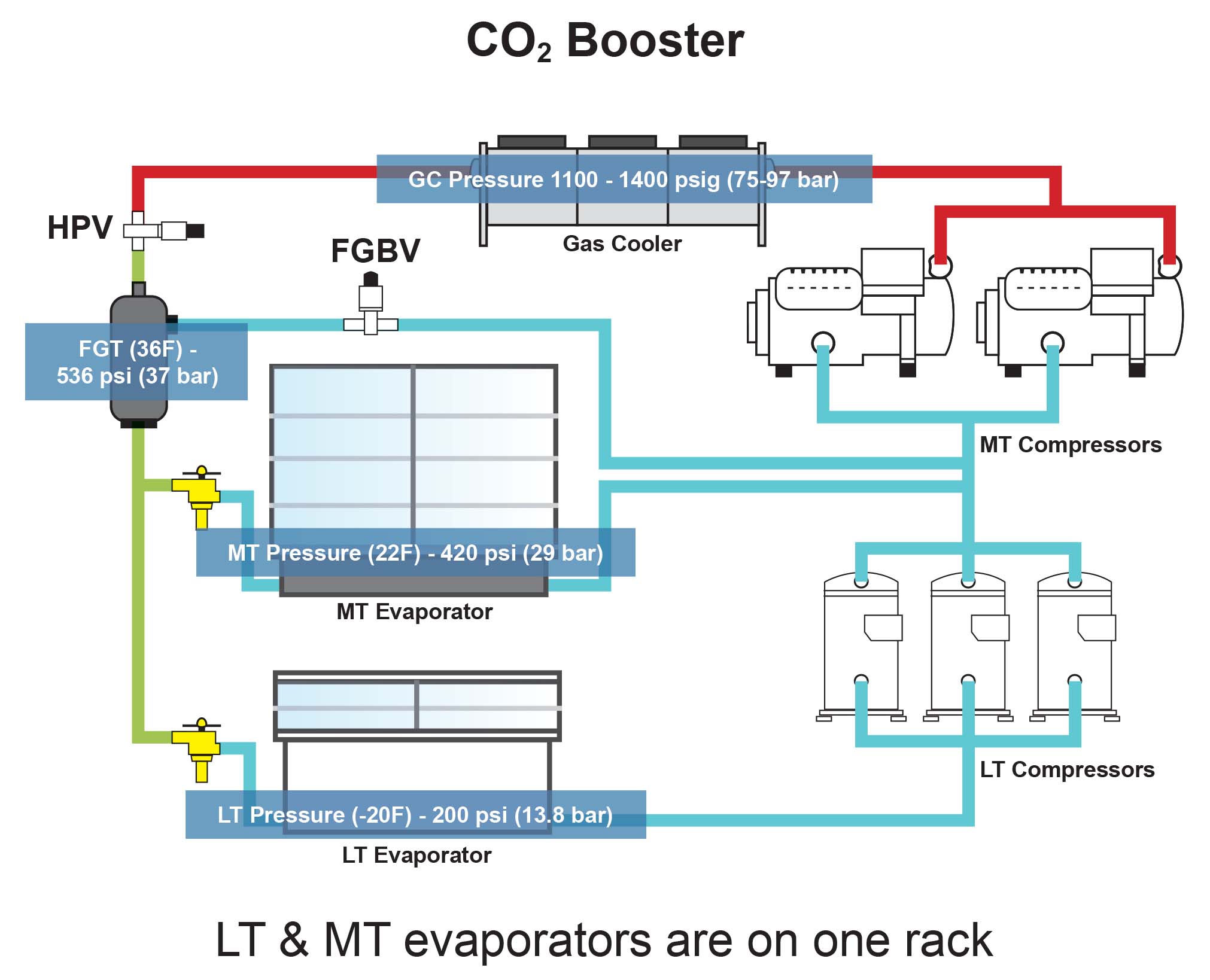
Although they have different names, all system components are basically located in the same areas (see Figure 1 below). Explain to students that with the CO2 booster, we are not changing what they have learned about how heat is removed; we are using a different refrigerant but similar components. For instance, the condenser in the R-404A diagram is doing a similar job as the gas cooler in the CO2 booster diagram. However, because the pressures are so high with CO2, the change from a vapor to a liquid must take place downstream.
Click diagram to enlarge
FIGURE 1: The R-404A DX uses a condenser, while the CO2 booster system uses a gas cooler. (Courtesy of Heatcraft)
One difference between an HFC unit and a CO2 booster unit is the rack system — with the HFC refrigerant system, the low- and medium-temperature rack systems are not combined. With the CO2 booster, both the low- and medium-temperature loads can be supplied by the same booster rack.
Step Two: Emphasize Safety
The next step in teaching students about CO2 is to talk about safety. In any service or repair refrigeration work, emphasize the necessity for personal protective equipment, including gloves, glasses, and safety shoes. The safety instructions for working with CO2 are the same as they are for other refrigerants:
- Prevent liquid from reaching the compressor;
- Provide a pressure relief valve (PRV) for overpressure protection;
- Prevent excessive vibration;
- Ensure proper alignment of piping to prevent connection stress;
- Protect external surfaces from corrosion; and
- Take precautions to avoid refrigerant contact with skin due to risk of frost or burn.
It cannot be overstated that students must know and understand how to work with CO2 safely. Because CO2 has no odor, a gas detection device is paramount. Warning signs — and sometimes respirators — will be installed wherever CO2 systems are located. The equipment, too, comes with safety features, such as high-pressure relief valves (HPRVs). Most importantly, those working on CO2 units must follow the rules and keep their eyes open.
Step Three: PID Diagram
The piping and instrument diagram (PID) is a roadmap that identifies every component, sensor, and safety and bypass valve in a working CO2 system, so it is important that the service technician understands how to navigate it. For instance, the included engineering notes in this troubleshooting tool even explain what type of piping should be used, as well as the bypass locations, allowing technicians to only shut down that part of the system that needs repair.
Step Four: Learn the SOO
Students need to understand the sequence of operation (SOO), so they know what to expect when the system actually starts to cool. Take for example, a fairly simple refrigeration system, where the medium-temperature compressors push the gas up to the gas cooler. From there, it goes to the high-pressure expansion valve (HPEV), which brings the pressure (and temperature) down. When the pressure is low enough, it changes to a liquid and is stored in the flash tank.
Step Five: Discuss Major Components
Be sure to allocate time to discuss the construction, installation, operation, and basic troubleshooting of all the components and the role they play in a system. This includes the CO2 compressor, temperature sensors, HPEVs, pressure sensors, and HPRV valves.
Step Six: Identify Best Practices
It is important for students to understand the best practices that should be employed when installing, starting up, and commissioning a CO2 system. Under this general topic, instructors must stress the tasks that are similar to those involved with installing and servicing HFC systems. However, students should understand that all tools, test devices, and valves must be pressure-rated for use on CO2 equipment.
Piping, brazing, and evacuation practices are virtually the same, but charging must be more deliberate at the flash tank. For example, the service technician must be careful to avoid the triple point. This means that only CO2 vapor should be introduced into the system until the pressure rises above 75.1 psia. If liquid CO2 is introduced into the system before this pressure is achieved, dry ice can form in the sealed system. Solids in a sealed refrigeration system are never a good idea.
When charging the system, a safe pressure to begin the switchover from vapor to liquid charging could be in the 100 to 150 psia range — a range in which no dry ice can form. If the rack being started is a medium-temperature/low-temperature (MT/LT) transcritical booster system, the MT compressor(s) must be started first, giving the MT loads time to stabilize. Then the LT compressor(s) can be brought online. Once the mid-tank sight glass clears, the startup technician can begin checking the loads as they begin pulling down to the set temperature.
Note that the controllers for CO2 systems are quite complex, and they will likely be handled by an HVACR controls specialist or integrator. The installing technician will need to verify that all temperature and pressure sensors are located properly throughout the system and that the leak detection probes are properly placed and wired. Students will also need to learn about the different types of copper that may be used on the same job — sometimes, even stainless steel piping is employed on the same rack.
Learning about refrigerants such as CO2in the classroom will teach students why each component does what it does, and overall, that makes for better troubleshooters and better servicers of the equipment. Still, there’s simply no substitute for experience. While we, as instructors, can philosophically talk about installing a unit, on-the-job training is essential, and it is the final best practice for all of our students to follow.
Whether you require installation, repair, or maintenance, our technicians will assist you with top-quality service at any time of the day or night. Take comfort in knowing your indoor air quality is the best it can be with MOE heating & cooling services Ontario's solution for heating, air conditioning, and ventilation that’s cooler than the rest.
Contact us to schedule a visit. Our qualified team of technicians, are always ready to help you and guide you for heating and cooling issues. Weather you want to replace an old furnace or install a brand new air conditioner, we are here to help you. Our main office is at Kitchener but we can service most of Ontario's cities
Source link