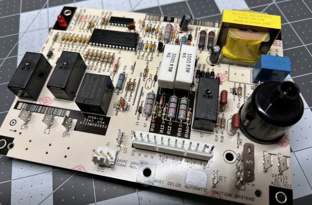
Technicians who have been in the HVAC industry for 20-plus years have noticed an ever-increasing and, oftentimes, frustrating number of printed circuit boards (PCBs) in their units. One popular manufacturer is now boasting seven separate PCBs in their standard 10-ton rooftop units. In trade school, we were taught to think about PCBs in simple terms; namely: “If you have the correct inputs but do not have the correct outputs, replace the board.” This troubleshooting technique works fine for PCBs with simple discrete inputs and outputs, but today’s PCBs are not as simple.
Many PCBs use low voltage PWM (pulse width modulation) signals, hall effect sensors, analog inputs, and analog outputs. Others have serial communication between separate PCBs. If you dabble in the controls business, you may even come across a protocol known as HART that uses serial communication and a 4-20mA analog signal over the same wires at the same time!
In short, due to ever-increasing levels of technology, misdiagnosed PCBs have become commonplace. Of course, part of our due diligence is a visual inspection for any broken traces or components that look like they’ve exploded or caught fire. But what does the average technician do after spending several hours troubleshooting a unit with no success? He throws a board at it. We’ve all done it.
Starting Your Journey with Electronics
If you want to be a valuable service technician primed for the future, it’s time you begin your journey with electronics. I’m not saying that circuit board repair is now part of your job description, but I am saying that familiarizing yourself with PCBs will greatly quell the intimidation factor that PCBs present to most technicians.
(And once you’re done with this article, further expand your high-tech skills with @benreed’s “Guide To Wireless Communications“).
I can give you a recent example: A boiler technician called me to assist with troubleshooting two boilers that had multiple circuit boards. Both independent boilers were giving the same error code. Knowing that a misdiagnosis would be a very costly mistake, he had called me for a second opinion. After thoroughly describing his troubleshooting process, he pointed to what he thought was the main board, explaining why it must be the culprit.
I agreed with his assessment but disagreed with which board was the “main board”. He had assumed that the larger board with all the “computer chips” on it must be the main board where the “brains” were at. As I examined the board, I noticed that these ICs (integrated circuits) were just darlington arrays and comparators. On a much smaller board, however, I found a small IC that had ATMEL printed on it. Having programmed many ATMEL microcontrollers, I knew this board contained the “brains” we were looking for.
Two boards were ordered. Two boilers were repaired. Not a dime wasted.
Understanding PCB Basics
The first principle you need to embrace is that it is not beyond your capabilities to have a decent understanding of boards, their layout, their design, and the function of each component. A common misconception amongst us HVAC technicians is that the engineers who design these boards and program them are all summa cum laude graduates. While this is true on some occasions and most of them are truly intelligent, they are not much different than us. Although they may have received degrees in electrical or electronics engineering, much of their trade study, like ours, has been self-taught at home.
Simply put, if you can grasp the complexities of HVAC systems and refrigeration, you can understand the basic operating principles of the circuit boards found in HVAC equipment without too much trouble.
Examining a Common PCB: The Carrier Ignition Control Module
Let’s begin by examining a common PCB found in many Carrier rooftop units, the Carrier Ignition Control Module (LH33WP002). I chose this board not only because it is common but because it is simple and it uses easy to identify TH (through-hole) components.
If you look closely, you will see small letters and numbers next to the components.

Understanding PCB Designators
These are called “designators”. Their primary purpose is for component assembly during the manufacturing process, but they are also used during the design and repair phases. The PCB designer will usually submit a BOM (bill of materials) spreadsheet that lists the specific components and their designators along with the Gerber files (board layout and design files) to the PCB manufacturer/assembler.
Here is a list of the designators used on this Carrier board and what they refer to:
- R = Resistor
- C = Capacitor
- D = Diode
- Z = Zener Diode
- T = Transformer
- J = Terminal Block (sometimes designated as “P” – Pin)
- JW = Jumper Wire
- U = Integrated Circuit (IC)
- K = Relay (Key Switch)
- Q = Transistor
- F = Fuse
- LED = Light Emitting Diode
Here are a few designators commonly found on other boards:
- L = Inductor
- X = Crystal
- SW = Switch
As you can see, many of these are intuitive and easily remembered, while others are arbitrary. These letters and numbers are printed on what PCB manufacturers call the “silkscreen layer”. You will also notice that underneath the component, there are component outlines. Components that are polarity sensitive, such as electrolytic capacitors and diodes, will have the polarity indicated on the silkscreen as well.
PCB Components and Markings
The silkscreen is also where you will find important information like “CUT IF CS USED” as well as the model number for this specific board. Keep looking and you will find where it says “GROUND SCREW REQUIRED” in the bottom right corner. If you turn the board over, you will see that this tubular stand-off is electrically connected to the ground plane of the PCB.

Where do you think the “brains” of this board reside? If you guessed the larger rectangular IC, you would be correct. On my particular board, this IC is marked as a Microchip CEPP130282-04. If you Google it, you will not find anything. That is because many manufacturers have custom designed chips or, as is likely the case here, have a non-public identifier printed on the chip. This is to prevent reverse engineering and to protect the intellectual property of the manufacturer or designer. This is very likely just the Microchip 8-bit PIC16C5 or similar microcontroller.

Understanding Microcontrollers
Let’s take a closer look at the microcontroller itself. In many cases, the public identifier will be printed on the IC. For example, a PIC16C57C can be found on the CXM board which was once used by Carrier and ClimateMaster in many of their water source heat pumps (not to be confused with the CXM2 which uses the STM32 microcontroller). We can work with this part number to dive a bit deeper into the brains of the Carrier Ignition Module.
One thing you will quickly learn is that finding data sheets on electronic components with public identifiers is much easier than finding service manuals to your HVAC equipment. Using a search engine, you can find what is called a “pinout” for this microcontroller.

In the top center of the IC in the image, you will see a half-moon marking. If you look closely at the physical IC, you will see an indention on one end that matches this. This is called the orientation marker and, as the name suggests, ensures that the IC is oriented correctly when placed on the board during assembly. Sometimes these orientation markers are dots, dimples, notches, grooves, or just a slanted edge on one side of the IC.
Understanding Voltage and Component Markings
In case you didn’t know, applying high voltage directly to this controller will destroy it. This controller operates on 5 volts DC. Take a look at the pin assignments for pin #2 and pin #4. Pin #2 is marked VSS and Pin #4 is marked VDD. Here is where things might get a bit confusing and counter-intuitive. VSS stands for Voltage Source Supply and VDD stands for Voltage Drain-to-Drain.
One might assume that Voltage Source Supply would be the positive voltage supplied to the IC and that the “drain” would be the negative. It is actually reversed in most cases. The reason for this is that these terms are rooted in the structure of a component called a MOSFET, where the “drain” terminal is connected to the positive supply voltage in an N-channel device. Don’t let this derail you. Let’s look at another component.

Understanding Capacitor Markings
This is a ceramic capacitor. It is marked “103Z”. The number 103 tells us what the capacitance is, just like our common run capacitors are marked 30μF or 45MFD. However, this is not a 103μF capacitor. It is actually only 0.01 microfarads, or 10 nanofarads. How did they come up with that? The first two numbers in 103 are the significant figures, and the last number (3) is the multiplier. Ten to the power of 3 (10x10x10 = 10,000), but our units are almost always in picofarads. So 10,000 picofarads = 10 nanofarads = .01 microfarads. The letter “Z” at the end is something that is manufacturer-specific, but likely indicates the tolerance (e.g. ±20%).
The purpose of this specific capacitor, and the reason it is located so close to the microcontroller, is that it is a “decoupling” capacitor. These are almost universal components for microcontrollers and they are connected between the positive and negative pins. It is also imperative that they be located as close as possible to the microcontroller VSS and VDD pins. The main purpose of a decoupling capacitor is to filter out high frequency noise and fluctuations from the power supply. The microcontroller is a very sensitive device and its processes can be interrupted by the slightest instability in the power supply.
Conclusion
The next time you have to swap one of these boards out because the induced draft motor will not come on, take the old one home and spend some time studying it. Just being able to identify each component will help alleviate any apprehension and hopefully spark a curiosity to dive deeper.
For more insights into HVAC troubleshooting and diagnostics, check out our comprehensive guide to success in the HVAC industry.
Whether you require installation, repair, or maintenance, our technicians will assist you with top-quality service at any time of the day or night. Take comfort in knowing your indoor air quality is the best it can be with MOE heating & cooling services Ontario's solution for heating, air conditioning, and ventilation that’s cooler than the rest.
Contact us to schedule a visit. Our qualified team of technicians, are always ready to help you and guide you for heating and cooling issues. Weather you want to replace an old furnace or install a brand new air conditioner, we are here to help you. Our main office is at Kitchener but we can service most of Ontario's cities
Source link


