This is the second article in Jordan Day’s series on Demystifying the Printed Circuit Board. Find Part 1 here.
Key Takeaways
- SMT vs Through-Hole: Modern HVAC boards use surface-mount technology (SMT) for compact design while still incorporating through-hole components for larger capacitors
- Trace Width Matters: PCB traces vary in width based on current requirements—wider traces handle relay outputs while narrow ones carry digital signals
- Voltage Regulation Chain: Boards step down from 24VAC to 12VDC for relays, then to 5VDC for microcontrollers using both linear and switching regulators
- Protection is Critical: Metal Oxide Varistors (MOVs) protect relay contacts from voltage spikes that can reach 300-400V when coils de-energize
In my last article, we took a look at the Carrier Ignition Control Module (LH33WP002). It was a very simple, single-layer PCB that consisted of through-hole components. This time we’ll examine a board that exhibits a few more modern features such as SMT (Surface-Mount Technology) and switching regulators. I realize some of this subject matter can be intimidating to techs who, like me, turn wrenches and strike torches. The reason we’re going to dig deep here is because the industry has left us no choice. We can get into the weeds and learn how these things work, or we can be left behind.
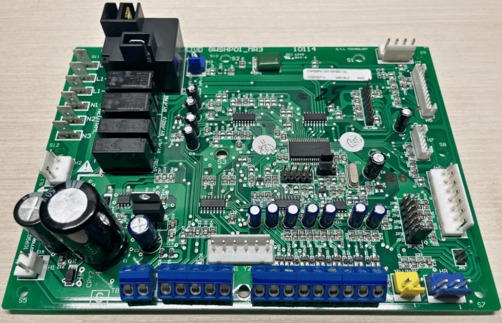
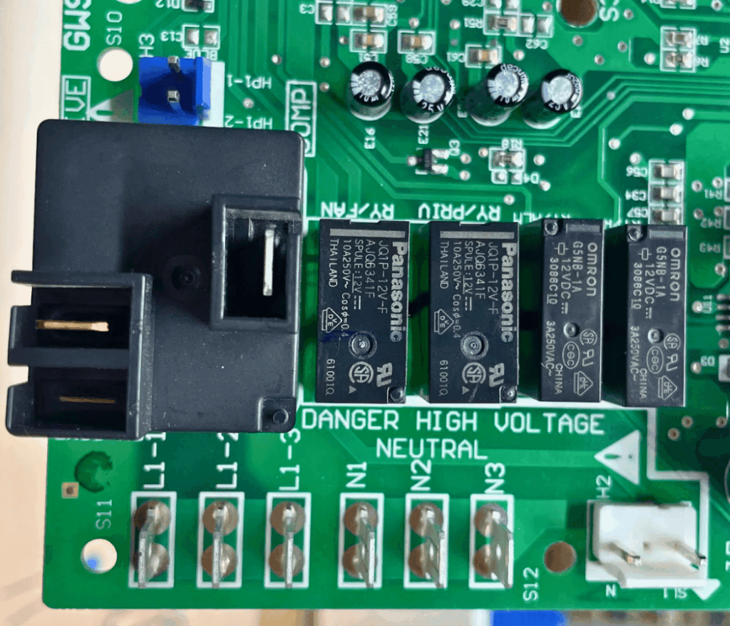
This is Daikin’s MTIII WSHP base controller that is found in many of their water source heat pumps.
While this board still uses some through-hole components, such as the large electrolytic capacitors, all of the ICs (Integrated Circuits) are SMDs (Surface-Mount Devices). Unlike through-hole parts with pins that pass through the board, SMDs sit directly on copper pads, with their small ‘feet’ soldered to the surface of the PCB.
The SMT Manufacturing Process
At the factory, the SMD is typically joined to the PCB by a process known as reflow soldering. This is where a solder paste (tiny solder particles suspended in flux) is printed onto the PCB pads using a stencil. Pick-and-place machines precisely position the SMDs onto the paste before going through the reflow oven. In the oven, the board is gradually heated, melting the solder particles in the flux. This allows it to flow around the pad and the feet of the SMD component before moving to the cooling process.
Understanding Multi-Layer Boards
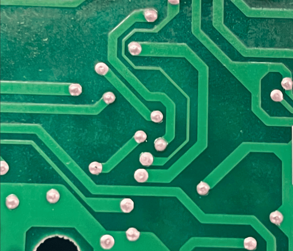
Another feature this board has that we didn’t see on the Carrier board is the use of two layers. The MTIII controller has traces printed on both the front and back. This allows the board to be more compact, since electrical pathways can cross over each other on separate layers without needing extra space or complicated routing on a single side. But how do electrical signals get from one side of the board to the other?
A tiny plated hole called a via acts as a conductive tunnel, connecting traces from the top layer to the bottom layer. This lets signals and power jump between layers, keeping the routing efficient and the overall board size smaller. Without vias, a two-layer or multilayer board wouldn’t really be possible. Interestingly, the holes used for through-hole components also serve a second purpose. Since they’re plated with copper, they connect the front and back layers of the board just like a via does. In other words, many through-hole components are already doubling as a via. Take a look at some of the vias used on this board.
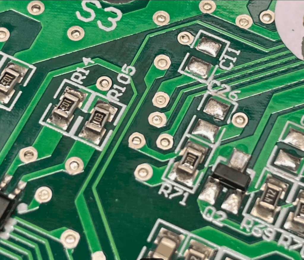
PCB Trace Design and Current Handling
You may have already noticed the big differences in trace widths on this board. Some are hair-thin while others are much wider, and a few even change width along their length. Why would some traces need to be different? Just as with wire sizing, more copper can safely carry more current. Certain signals, like the digital inputs feeding into the microcontroller, require very little current and therefore only need very narrow traces. Relay outputs, on the other hand, may have much more current flowing through them and must be given wider traces to handle the load reliably.
Understanding trace layout is similar to reading HVAC wiring diagrams—once you understand the flow of power and the purpose of each connection, the entire system starts to make sense. Wider traces also help spread out the heat created by higher currents, preventing hot spots on the board. Another factor that is not clearly visible upon inspection is “copper weight”. The standard copper weight for outer layers of a PCB is 1oz per square foot. While this board does not have any inner layers, they are typically 0.5oz per square foot. Thicker copper traces, like 2oz or 3oz per square foot, may be ordered to carry more current without taking up as much board real estate.
The Microcontroller: The Brain of the Operation
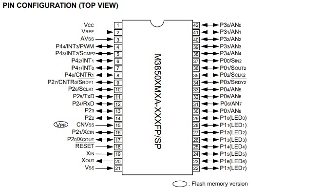
Let’s get into some of the components that we didn’t see on the Carrier board. The microcontroller used on this board is the M3850 by Renesas Electronics.
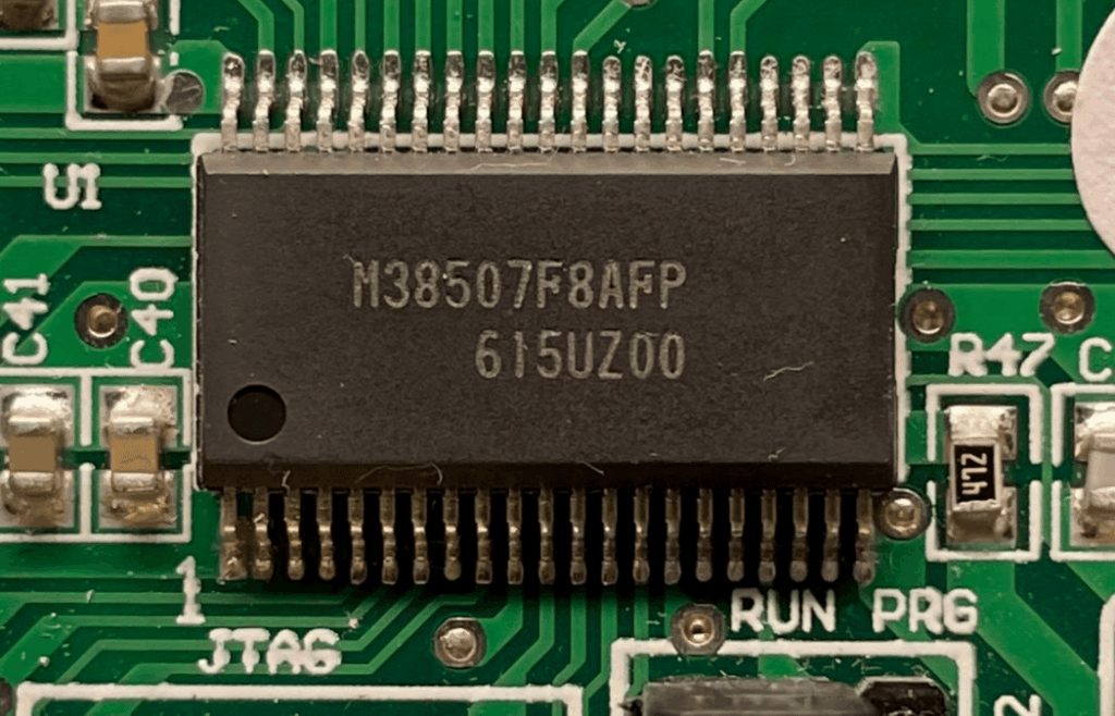
The data sheet shows that the power supply input for this microcontroller unit (MCU) is 2.7 VDC – 5.5 VDC. This particular one we are looking at on our Daikin board is fed with 5 VDC. The positive of the supply is routed to pin 1 (VCC – Voltage Common Collector) and the negative is routed to pin 21 (VSS – Voltage Source Supply). These markings can get confusing for us HVAC techs. The datasheet for the MCU used on the Carrier board we last looked at had the positive pin marked “VDD”. This is used interchangeably in most cases with “VCC” and is almost always the positive connection point.
Voltage Regulation: From 24VAC to 5VDC
As mentioned in the last article, applying our 24 VAC directly to the MCU will destroy it immediately. How does the voltage get stepped down to 5 VDC? That is where the L7805 voltage regulator comes into play.
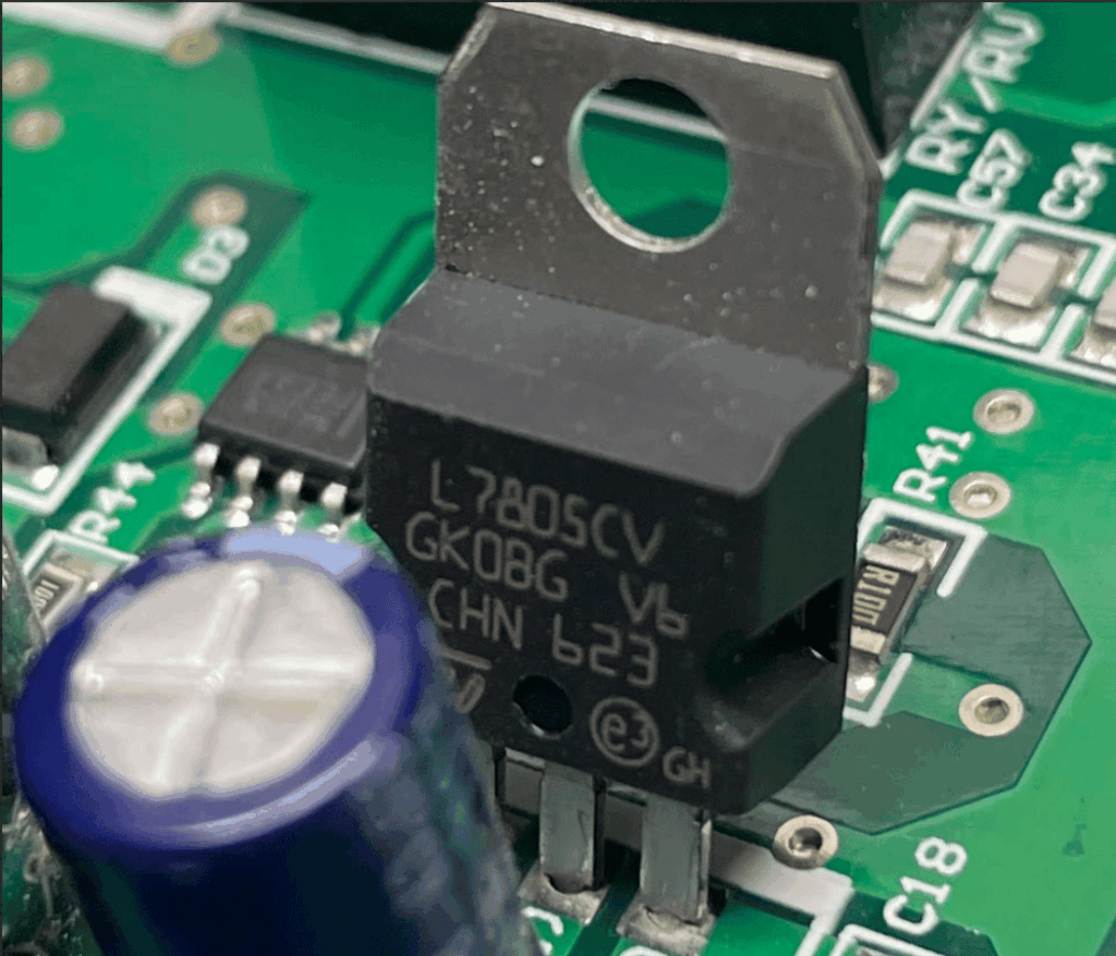
This classic linear voltage regulator takes a higher DC voltage like 24 VDC and steps it down to 5 VDC. But let’s not assume that is exactly what’s going on here. First, if we fully rectify 24 VAC RMS and smooth it with capacitors, the resulting DC voltage will reach approximately 33 V, which corresponds to the peak voltage of the AC sine wave. Although the L7805 datasheet specifies a maximum input voltage of 35 V, using voltages that high would generate significant heat at typical load currents and would require large heatsinking, so it is generally not recommended.
This sensitivity to incoming voltage is why understanding utility over-voltage conditions is crucial for technicians. When utility voltage rises above normal levels, it can push these regulators beyond their safe operating limits, leading to premature board failure. So are there any other clues about what voltage is being fed to the regulator? Let’s look at the on-board relays.
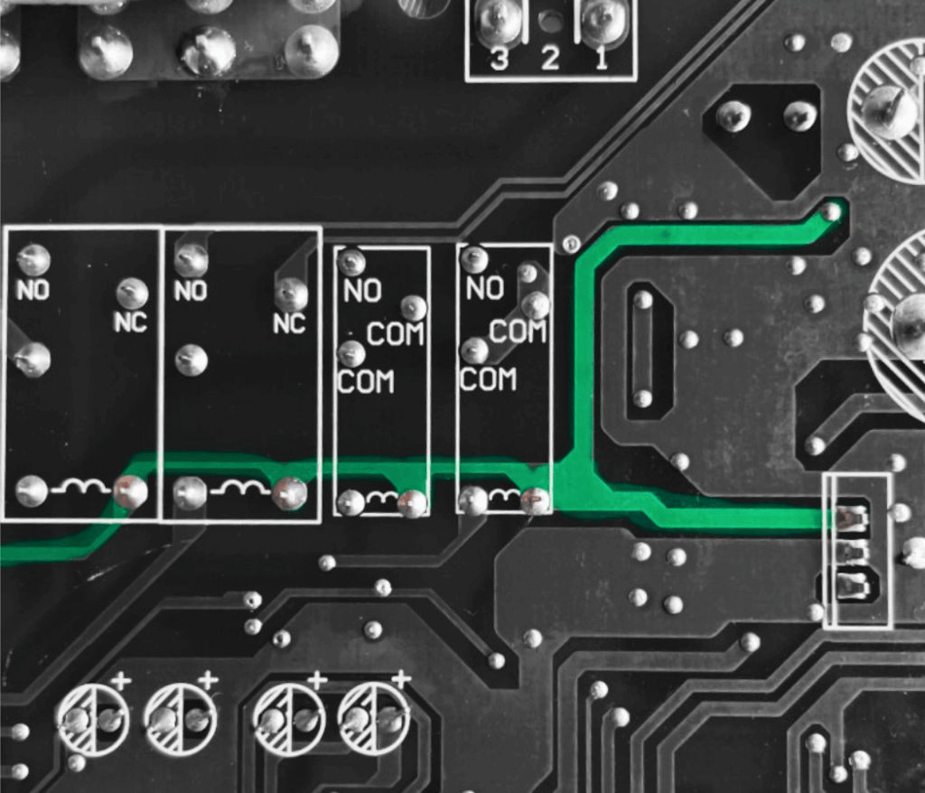
These relays have 12 VDC coils. On the back of the board, we can see by the PCB traces that the coils are powered from the same source as the input pin for our L7805 regulator.
Switching Regulators: Efficient Power Conversion
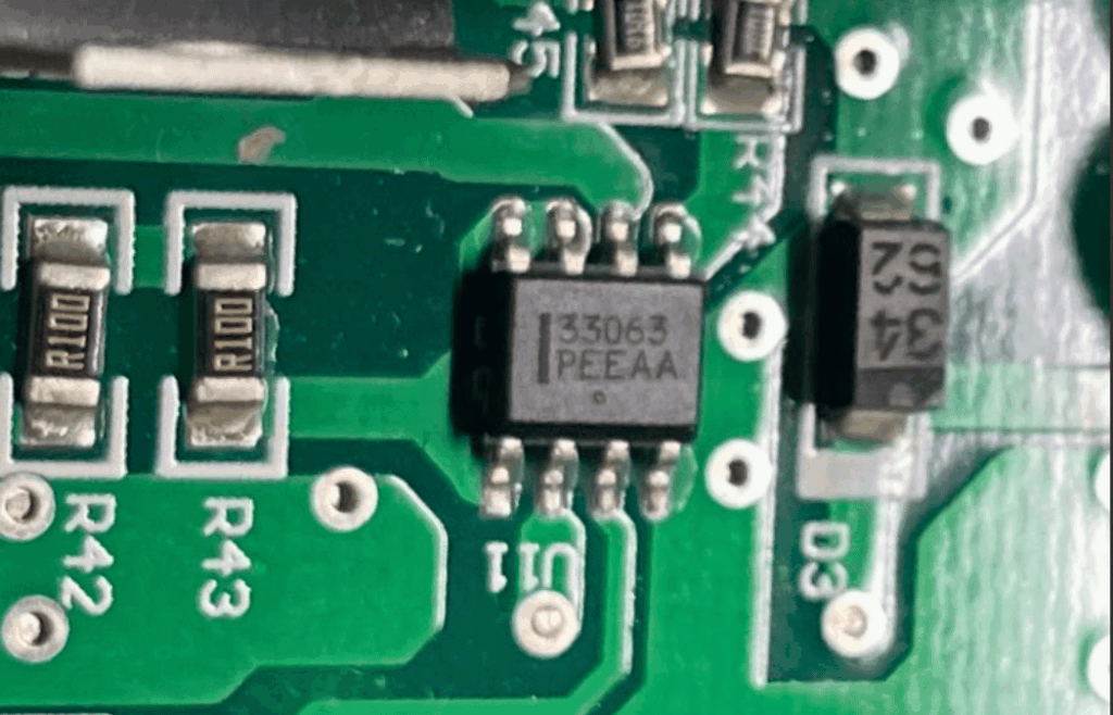
This means we must have another voltage regulator somewhere. If we look near the large 2200μF capacitor, we’ll notice a very small IC labeled “33063”. This is a switching regulator. Unlike linear regulators, which waste excess energy as heat, a switching regulator turns on and off rapidly to maintain the desired output voltage. The output voltage is determined by the value of two resistors forming a voltage divider circuit that is fed back to the comparator on pin 5. These devices tend to cost more, but they run much cooler and are far more efficient.
Understanding PCB Relays
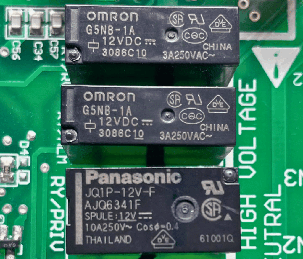
Did you notice there are five relays on this board? And three different types? Why wouldn’t they all be the same? Just like the contactors we HVAC technicians frequently replace, amperage rating matters. While your common Eaton 3-pole contactors with 30-amp inductive ratings might look identical to your 50-amp versions, the same can’t be said for PCB relays. Smaller relays generally have lower current ratings, and since PCB real estate is expensive, designers usually choose the smallest relay that can handle the job.
On this board, we have two Omron 3-amp relays, two Panasonic 10-amp relays, and one Omron 30-amp relay. Out in the field, we often see these onboard relays doing nothing more than controlling a contactor (or a larger relay) and switching 500 mA of current or less, even though they’re rated to handle much more. This is similar to how we use capacitors in motor circuits—often with significant safety margins built in.
Transistor Arrays: The Interface Between Low and High Voltage
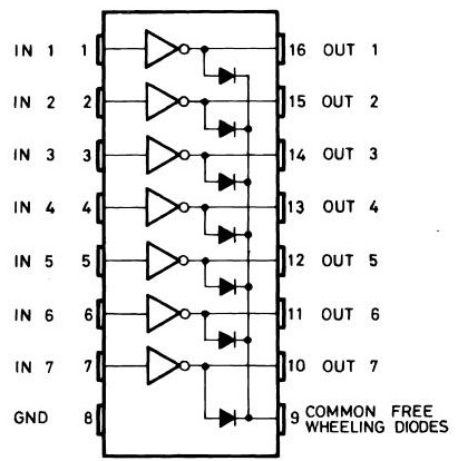
But how can a PCB relay with a 12VDC coil be switched ON/OFF by a microcontroller that can only handle a maximum of 5.5VDC? This is where the magic of the transistor comes into play. A Darlington transistor array known as a ULN2003 can be located just above the microcontroller.
The microcontroller’s outputs are connected to the ULN2003’s inputs, and the ULN2003’s outputs are connected to one side of each relay coil. As shown in one of the images above, the 12 V power rail traces connect to the other side of the coils. When a transistor is triggered by its input, it allows current to flow through it to ground, completing the circuit and energizing the relay coil. Another reason you’ll find this handy little IC on so many PCBs is that it includes built-in flyback diodes to protect the circuit from voltage spikes that occur when a relay coil is switched off.
Crystal Oscillators: Keeping Perfect Time
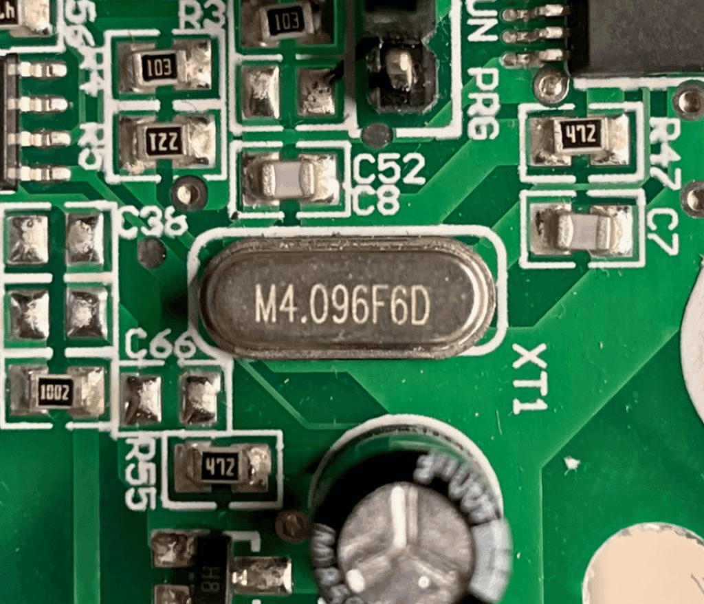
Right next to the microcontroller, there’s a small metal can marked M4.096F6D. This is a crystal oscillator. Its job is to keep the microcontroller running on a steady clock signal. The number tells us it runs at 4.096 MHz, which means it vibrates over four million times per second to keep everything in sync. The microcontroller uses that timing to run its program at the right speed and to make sure things like communication and internal timing stay accurate. Without it, the microcontroller would have no sense of timing and wouldn’t operate reliably.
Input Signal Processing: From 24VAC to Logic Levels
How does the microcontroller know when there is a call for heat or cooling? Every HVAC technician knows that our thermostat usually gets 24VAC from the R terminal of the board and then sends it back to terminals G, Y, O, etc. How can our microcontroller see those 24VAC signals if those signals would destroy it?
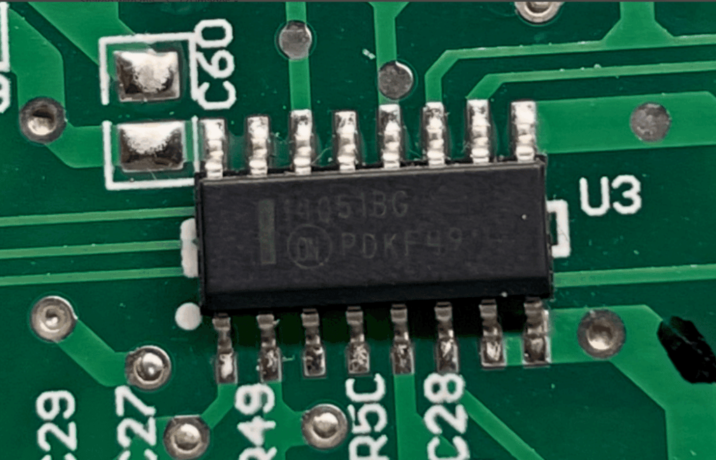
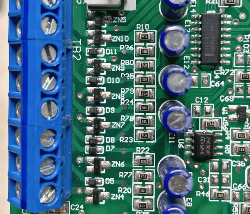
When the 24VAC signal enters the board, it first passes through a small diode and a series 3 kΩ resistor (marked 3001). This combination rectifies the AC and limits current to protect downstream components. From this node, the signal encounters a voltage divider formed by the 3 kΩ series resistor and a 4.7 kΩ (marked 472) resistor to ground, which drops most of the voltage. A Zener diode to ground then clamps the voltage to a safe level for the IC, while a 47 μF capacitor smooths the half-wave rectified signal into a more stable DC voltage.
The result is a clean signal around 3.2 VDC, high enough to register as a logic HIGH but safely within the voltage limits of the circuitry. This node feeds pin 1 of the 14051 analog multiplexer IC, which acts as a switch controlled by select lines from the microcontroller. The multiplexer allows multiple signals to share a single MCU pin, so the microcontroller can read this input without needing a dedicated pin for every signal. Beyond saving pins, the multiplexer also isolates each input, preventing voltage spikes, noise, or conflicts from affecting the microcontroller, making the overall system both efficient and safe.
This multiplexer concept is similar to how modern boards handle wireless communications—efficiently managing multiple data streams through shared resources. Understanding these input circuits is useful when applying general HVAC troubleshooting principles to control board diagnostics, where signal integrity directly affects system operation.
Take Your PCB Knowledge to the Field
Do you feel like you’re drinking from a firehose? That’s completely normal if you’re new to PCB circuit analysis. If you take away nothing else from this, just know that understanding these concepts is not beyond your reach. As a competent commercial HVAC technician, you already handle systems just as complex—they’re simply larger in scale. The more PCBs you study, the more you will find repeating patterns and usage of common ICs.
Ready to expand your commercial client base? Understanding advanced electronics is just one way to set yourself apart from the competition. Property.com’s ‘Know Before You Go‘ tool helps skilled technicians leverage their expertise by providing detailed insights into commercial properties—including system age, maintenance history, and upgrade opportunities. This valuable intelligence allows you to approach potential clients with targeted solutions based on their specific needs. Join the exclusive network of certified pros who are using data-driven insights to grow their commercial service business.
Whether you require installation, repair, or maintenance, our technicians will assist you with top-quality service at any time of the day or night. Take comfort in knowing your indoor air quality is the best it can be with MOE heating & cooling services Ontario's solution for heating, air conditioning, and ventilation that’s cooler than the rest.
Contact us to schedule a visit. Our qualified team of technicians, are always ready to help you and guide you for heating and cooling issues. Weather you want to replace an old furnace or install a brand new air conditioner, we are here to help you. Our main office is at Kitchener but we can service most of Ontario's cities
Source link