Initially Revealed on Tim De Stasio HVAC
It’s essential for an HVAC technician to grasp air move and the way blowers and followers carry out beneath numerous circumstances.
These relationships are expressed within the 3 fan legal guidelines, that are mathematical formulation.
Whereas designers should use these legal guidelines quantitatively when sizing and choosing tools and ductwork, a service technician also needs to perceive them qualitatively- as in how altering fan velocity or static stress impacts airflow and horsepower.
Fan Legislation 1: CFM is straight proportional to RPM.
System: CFM2= CFM1 X (RPM2 ÷ RPM1) or RPM2= RPM1 X (CFM2 ÷ CFM1)
What it means: As you enhance fan RPM, CFM will increase at a 1:1 ratio.
So if you must enhance CFM by 10%, your RPM has to extend by 10%.
Since it’s a 1:1 ratio, it additionally means we will interchange RPM for CFM in Fan Legal guidelines 2 and three.
We use Fan Legislation 1 on a regular basis within the subject. If we have to change airflow, we modify fan velocity both by altering a velocity faucet, VFD output, pulley diameter, or different means.
Apply it within the subject: In case your blower is shifting 1000 CFM at 1100 RPM, and you must lower airflow by 10% to 900 CFM, Fan Legislation 1 says your RPM should lower by 10% additionally. Let’s put that within the system:
RPM2= RPM1 X (CFM2 ÷ CFM1)
RPM2= 1100 X ( 900 ÷ 1000)
RPM2= 990 That is your new RPM.
We additionally want to grasp that for us to make predictions utilizing this fan legislation and fan legal guidelines 2 and three, all the pieces else in regards to the air and the system should keep the identical, together with air temperature and density.
System friction should additionally keep fixed, so these fan legal guidelines can’t be used with computerized dampers that self alter to take care of move.
Fan Legislation 2: Whole Static Stress adjustments with the sq. of CFM (or RPM).
System: SP2= SP1 X (CFM2 ÷ CFM1)² or SP2= SP1 X (RPM2 ÷ RPM1)²
What it means: A ten% enhance in CFM will end in a 21% enhance in Static Stress.
Take into consideration that.
A small enhance in airflow creates a major enhance in duct stress.
This elevated stress shall be evenly distributed throughout parts like coils and filters.
So this fan legislation could be utilized to Whole Static Stress or a Static Stress drop throughout a single part within the system.
That issues as a result of some parts have static stress limitations that have an effect on their efficiency.
Air filters work greatest once they have a low stress drop throughout them, as a result of this normally means the air velocity is low sufficient to permit for “dwell time” via the filter materials, catching extra particulates.
Condensate traps which are already near their restrict could need to be made deeper, in order that they don’t get overwhelmed.
Air proving switches have to be adjusted in order that they do their job on the new CFM and Static Stress.
Apply it within the subject: At 1000 CFM, you learn a 0.15″w.c. stress drop throughout a media filter.
That you must enhance your airflow to 1200 CFM. What would be the new stress drop?
SP2= SP1 X (CFM2 ÷ CFM1)²
SP2= 0.15 X (1200 ÷ 1000)²
SP2= 0.26″ w.c. This new stress drop will most likely be too excessive, in accordance with most filter producer specs that suggest lower than 0.2″. It’ll carry out like a unclean filter, even when model new.
The filter floor space now needs to be elevated.
Utilizing Fan Legislation 2 to foretell Static Stress will forestall you from creating unintended penalties by growing airflow on a system that’s already near its restrict.
Fan Legislation 3: Horsepower adjustments with the dice of CFM (or RPM)
System: HP2= HP1 X (CFM2 ÷ CFM1)³
What’s means: A ten% enhance in airflow leads to a 33% enhance in horsepower required to try this work. In case your motor is already near its rated HP, a small airflow enhance can overload it.
Let’s display that.
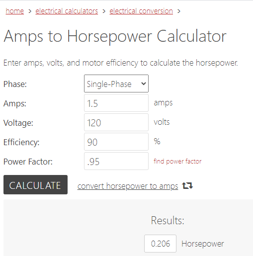
Apply it within the subject: At 1000 CFM, your blower attracts 1.5A.
That you must understand how a lot HP it makes use of now and what your new HP shall be whenever you enhance airflow to 1200 CFM.
Use an amps to hp conversion software to calculate HP1 within the Fan Legislation System.
You’ll need to know or make an informed guess what the motor effectivity and energy issue is.
As you may see under, HP1 is 0.206 HP.
Now, what occurs to HP2 once we enhance the airflow from 1000 to 1200 CFM?
HP2= HP1 X (CFM2 ÷ CFM1)³
HP2= 0.206 X (1200 ÷ 1000)³
HP2= 0.355. That is your new HP requirement.
What occurs in case your motor is just one/3 HP (0.333)?
Your motor shall be overloaded and won’t final lengthy.
You’ll have to step as much as a 1/2 HP motor.
Wouldn’t that be good to know earlier than proposing the airflow change?
Fan Curve Charts
Producers check their tools beneath quite a lot of circumstances and plot fan efficiency on a “Fan Curve Chart.”
That is helpful for predicting how the efficiency adjustments as different variables change.
Fan curve charts look completely different from producer to producer.
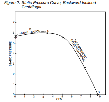
Most appear to be a graph, as proven under.
The curve represents a relentless RPM for a particular mannequin.
Plot a horizontal line beginning on the Static Stress axis till it intersects with the curve.
Then plot one other line straight all the way down to the CFM axis. That is the CFM at these circumstances.
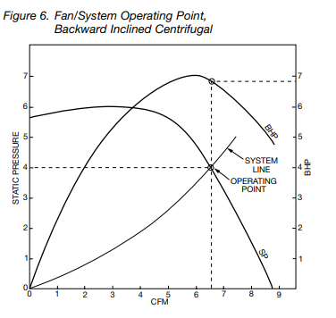
Some producers add a Brake Horsepower (BHP) curve to this chart to indicate how a lot energy is required to do the work we’re asking the fan to do at a given RPM and SP.
This intersection known as the Working Level.
When a BHP curve is added, we will decide the Horsepower required by plotting a vertical line up from our Working Level to intersect with the BHP curve.
Utilizing the three Fan Legal guidelines with a Fan Curve Chart
The producer will at all times present a “System Line” that represents the trail the fan has to remain on as circumstances round it change.
Any level plotted on the chart have to be alongside the System Line.
As soon as an Working Level could be plotted on a fan curve chart at a recognized RPM, we will now use the three fan legal guidelines to foretell what is going to occur if RPM or SP adjustments.
CFM and Horsepower will change with RPM and SP adjustments.
Confer with the fan curve above.
Let’s assume the RPM curve is for 1000 RPM.
Assume the CFM models are X1000.
Let’s additionally assume that the Static Stress models are inches w.c.
Let’s faux on the given Working Level, this fan strikes 6500 CFM at 4″ w.c. The required BHP is 6.9.
What if we wish 6000 CFM as a substitute?
What is going to our new RPM be?
Fan Legislation 1: RPM2= RPM1 X (CFM2 ÷ CFM1)
RPM2= 1000 X (6000 ÷ 6500)
RPM2= 923. The fan needs to be slowed all the way down to this RPM to get the specified CFM.
What is going to our new SP be?
Fan Legislation 2: SP2= SP1 X (CFM2 ÷ CFM1)²
SP2= 4 X (6000 ÷ 6500)²
SP2= 3.4″ w.c.
What’s our new HP required?
Fan Legislation 3: HP2= HP1 X (CFM2 ÷ CFM1)³
HP2= 6.9 X (6000 ÷ 6500)³
HP2= 5.4
Choosing Tools Utilizing Fan Curve Charts
Producers present efficiency specs to permit designers to pick out the best fan for his or her system.
In residential design, we measurement the duct friction based mostly on the fan efficiency of the air handler we now have pre-selected based mostly on the tonnage our load calculation requires.
However in business design, we measurement the fan based mostly on the friction of the duct system we now have already designed.
In both case, we should seek the advice of the producer’s fan efficiency information to confirm the fan is an effective match for the load.
Train: Choose the higher exhaust fan for our business software. 1000 CFM @0.5″ w.c.
We’ve 2 selections: Greenheck Mannequin SQ-130-B or a smaller mannequin SQ-100-VG.
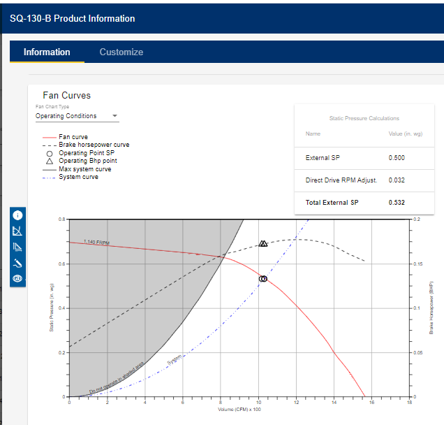
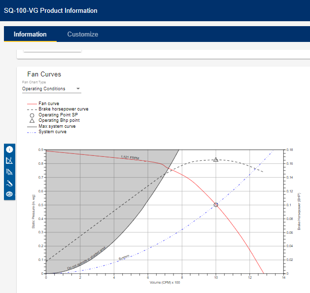
Each fashions will do the job.
Discover the bigger mannequin SQ-130-B operates at a decrease RPM (1140) in comparison with SQ-100-VG (1521).
Decrease RPM will normally imply quieter operation.
If noise is a priority, you could determine to pick out the bigger fan.
However the smaller mannequin requires much less BHP (much less wattage to run), and little doubt prices much less.
So if preliminary price and working price are a precedence, you would choose the smaller SQ-100-VG.
Discover, additionally, the shaded gray space.
That is thought-about the unstable space the place the fan doesn’t run quick sufficient to maneuver the air in a predictable approach.
That is known as the stall and surge impact.
Most producers now make the most of choice software program that robotically plots the design circumstances you enter into the fan curve chart, giving extra accuracy.
However it’s nonetheless essential to have the ability to learn a fan curve chart.
Remaining Ideas
In the end, a service technician ought to be capable of perceive the three Fan Legal guidelines to be extra correct when making airflow changes.
Business technicians, particularly ones that fee and steadiness tools, ought to be capable of learn fan curve charts to take the guesswork out of constructing changes or discovering potential design flaws.
Even in case you are not in these sectors of the business, having this information will at all times allow you to be a greater technician.
Whether you require installation, repair, or maintenance, our technicians will assist you with top-quality service at any time of the day or night. Take comfort in knowing your indoor air quality is the best it can be with MOE heating & cooling services Ontario's solution for heating, air conditioning, and ventilation that’s cooler than the rest.
Contact us to schedule a visit. Our qualified team of technicians, are always ready to help you and guide you for heating and cooling issues. Weather you want to replace an old furnace or install a brand new air conditioner, we are here to help you. Our main office is at Kitchener but we can service most of Ontario's cities
Supply hyperlink


Add Comment