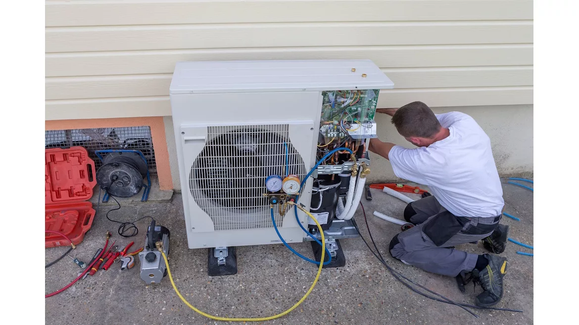
Your phone rings at 7:00 a.m. in January. The homeowner says their heat pump quit, and the house is freezing. When you pull up, there’s ice everywhere on the outdoor unit — a solid block covering the whole thing. This scenario happens thousands of times each winter, and how you diagnose the problem determines whether you solve it on the first visit or get called back the next day.
Accurate defrost diagnostics do three things for your business: cut callbacks, protect you from liability issues, and increase your revenue per service call. Part 1 of this series focuses on the defrost cycle. Part 2 covers reversing valve problems.
Heat Pump Defrost Basics
Some frost on the outdoor coil is normal during heating. Cold air passing over the coil leaves moisture that freezes. The defrost system is supposed to melt this ice off before it chokes the airflow.
The defrost board controls the entire process. It monitors temperature and pressure, manages when the reversing valve switches modes, and coordinates all the components. Here’s what happens during defrost: The system flips to cooling mode for a few minutes. Hot refrigerant rushes through the outdoor coil and melts the ice. The high-voltage relay kills power to the condenser fan. You need that hot gas sitting on the coil, not getting blown away. Meanwhile, the heat strips inside turn on, so the house stays warm.
Break any link in this chain, and ice piles up until the unit can’t heat anymore. Heavy frost, blocked fins, or ice coating the whole unit means defrost isn’t working.
Step-by-Step Defrost Troubleshooting
Do the same thing on every call. Walk the perimeter first. Check for broken wires, loose sensors, busted parts, or signs that squirrels got into the wiring. These simple issues cause half of all defrost failures.
Electrical Testing
Check the transformer voltage first. Grab your multimeter and set it to AC voltage. Put the leads on R and C at the defrost board. You’re looking for 24 volts. Low voltage means transformer problems or loose connections upstream.
Looking for quick answers on air conditioning, heating and refrigeration topics?
Try Ask ACHR NEWS, our new smart AI search tool.
Ask ACHR NEWS
Next, force a defrost cycle. Most boards have TEST terminals or jumper points. Jump these terminals and watch what happens. The reversing valve should click, auxiliary heat should activate, and the condenser fan should stop. If nothing happens, the board is likely dead.
Sensor Verification
Sensors go bad more than most HVACR techs think. Check the resistance and match it to the chart in the manual. Here’s the problem: A sensor can test fine, but still not talk to the board right. Test the sensor first. If it’s good but the board does nothing, swap the board.
Test both pressure switches by measuring voltage. Place one probe on Common and the other on R-PS1. You should read 24 volts leaving the board. Move to PS2 to check the voltage returning through the closed pressure switch. No voltage means an open switch or wiring problem.
External Factors
Check for water intrusion in junction boxes. Look inside the defrost board housing for bugs, lizards, or spiderwebs. These pests short out terminals and cause intermittent failures. Inspect all wire connections at the board. A single loose spade connector creates problems that seem random but repeat after every service call.
Defrost Board Terminal Guide
Understanding board terminals speeds up diagnosis. Each terminal serves a specific function in the defrost cycle.
Terminal | Function | Voltage |
R & C | Power input to board | 24V AC |
DFT | Power return from defrost temperature sensor | 24V AC |
W | Controls electric heat strips during defrost | 24V AC |
O | Power input to board | 24V AC |
O-RV | Power output to reversing valve solenoid | 24V AC |
R-DFT | Power output to defrost temperature sensor | 24V AC |
R-PS1 | Power output to check low-pressure switch | 24V AC |
PS2 | Power return through pressure switch | 24V AC |
C-RV | Common terminal for reversing valve | Common |
CNT | Power output after switches close and delay satisfied | 24V AC |
Y | Receives signal through high-pressure switch | 24V AC |
DF1 | Incoming power for condenser fan relay | 240V AC |
DF2 | Outgoing power to condenser fan motor | 240V AC |
This table gives you a quick reference in the field. Most misdiagnoses happen because technicians skip terminal voltage checks and guess the problem.
Get It Right the First Time
Document everything you find. Write down which component failed and why.
- Did moisture corrode a connection?
- Did a bug nest short out terminals?
- Did the sensor drift out of range?
This information protects you if the customer questions the repair.
Before you leave the job, run a complete defrost cycle and watch it finish. Don’t assume the repair worked because the board clicked. Wait until you see ice melting off the coil and the unit returns to normal heating. Those extra 10 minutes prevent callbacks that cost you money and damage your reputation.
Create a simple diagnostic chart for your truck. List the most common failure points and the tests that identify them:
- Voltage at transformer – confirms power supply to board
- Forced defrost test – verifies board can initiate cycle
- Sensor resistance – catches sensors reading incorrectly
- Pressure switch continuity – finds stuck or failed switches
- Terminal voltages – pinpoints exact failure location
Keep Learning, Keep Earning
ACCA provides technical training on heat pump diagnostics and system troubleshooting. These resources help you master the details that separate quick fixes from recurring problems. Visit acca.org to access training materials and certification programs.
Part 2 covers reversing valve diagnostics, including electrical testing, mechanical assessment, and internal leak detection. Master both defrost and reversing valve troubleshooting, and you’ll be able to handle 90% of winter heat pump failures on the first call.
Whether you require installation, repair, or maintenance, our technicians will assist you with top-quality service at any time of the day or night. Take comfort in knowing your indoor air quality is the best it can be with MOE heating & cooling services Ontario's solution for heating, air conditioning, and ventilation that’s cooler than the rest.
Contact us to schedule a visit. Our qualified team of technicians, are always ready to help you and guide you for heating and cooling issues. Weather you want to replace an old furnace or install a brand new air conditioner, we are here to help you. Our main office is at Kitchener but we can service most of Ontario's cities
Source link