Periods of instability in HVAC systems often occur during necessary transitions in system operation. Examples of such instances include when a system first enables, shifts from occupied to unoccupied mode, or when key components of the system (chillers, pumps, etc.) stage on or off to meet system demands.
Additional provisions in the automation of these systems are required to minimize the effects of these disturbances. Typically, not all the kinks are worked out prior to the functional performance testing directed by the commissioning provider. Our testing processes should pay extra close attention during transitional periods to identify any unexpected instability, and we should also have a solid understanding of the tools available to the temperature controls contractor to improve performance in such instances.
Last month’s column detailed an example of how additional provisions in the BAS programming were needed to prevent tripping chillers offline when rotating between chillers during periods of low system flow. This month’s column looks at how to prevent spilling condenser water out of the top of a cooling tower during such chiller rotations.
Chiller Rotation: Preventing Cooling Tower Spillover
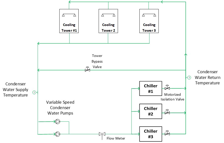
The chiller plant in question is the same plant we discussed last month. It consists of three water-cooled chillers and three cooling towers. See Figure 1. A single chiller can handle the relatively small cooling demand placed on the plant in the winter. However, to even out operating hours on the chillers, lead chiller rotation still needs to occur in the winter. Such rotation requires an overlap period when both the incoming lead and outgoing lead chillers are operating – see last month’s article for details. During that period of overlap, both chillers’ condenser water isolation valves are open and condenser water flow is split between the two chillers.
For this plant, the specified sequence of operation called for the condenser water pumps to modulate their speed to maintain condenser water flow at setpoint, a setpoint which was reset based on operating chillers. Thus, during the overlap period when the lead chiller designation is rotating, condenser water flow rate would be doubled from 2,500 GPM (one chiller operating) to 5,000 GPM (two chillers operating). The sequence pairs cooling towers with chillers; therefore, if two chillers are operating during the overlap period, then two cooling towers need to be operating as well.
Concerns were brought up during the temperature control submittal review process regarding how exactly wintertime chiller rotation could occur stably, since only one cooling tower was designated for wintertime operation. It was only that single winter tower that had a basin heater and heat trace on the system piping exposed to ambient conditions. The other two towers would be drained for the winter, and there would not be a second tower available to direct water to during the overlap period when both chillers were operating. That single winter tower was not rated to handle the flow rate of two chillers (5,000 GPM), and the concern was that substantial amounts of water would spill out the top of the cooling tower onto the central utility plant’s roof. We recommended the cooling tower bypass valve be opened to provide a second path for the additional condenser water flow experienced during the chiller rotation period. That recommendation was accepted by the design engineer, and a construction bulletin was issued with the change to the sequence.
Unfortunately, this construction bulletin was missed by the temperature controls programmer. While testing chiller rotation in winter mode (with only one cooling tower available), the condenser water flow rate doubled during the chiller overlap period. The bypass valve remained closed and double the condenser water flow was sent to the tower. Our concerns were validated (see Photo 1 below). A substantial amount of water was lost during each rotation, which would create an ice rink on the roof in the winter – not to mention the associated water waste.
Then came the iterative process of attempting to prevent this tower spillover from occurring in the future.
FIGURE 1: Condenser water system. (Courtesy of Questions and Solutions Engineering)
The Fix: Attempt 1
To minimize the programming adjustments to an already operational chilled water plant, the temperature controls contractor proposed just keeping the condenser water flow rate at 2,500 GPM (single chiller operating setpoint) during the overlap. This was a flow rate a single cooling tower could handle without spillover. Our initial concern was that splitting one chiller’s condenser flow between two chillers would result in condenser water flow trips at the chiller. We reviewed the chiller submittal and confirmed the minimum condenser water flow rate for the chiller as 830 GPM (well below the resultant 1,250 GPM each chiller would be getting during the overlap period in this scenario). The design engineer agreed this met the design intent of the construction bulletin, so we gave it a try.
After the minor programming adjustment, chiller rotation while in winter mode was tested again. There was still spillover, albeit less. The reason came from the fact that condenser water flow initially spikes when the second (incoming lead) chiller’s condenser isolation valve opens. The second path for flow results in a substantially less restrictive system curve, and the flow rate initially spikes before the condenser water pumps can slow down to again track the 2,500 GPM setpoint. See Figure 2 for a diagram.
The Fix: Attempt 2
As it turned out, we did need to open that cooling tower bypass valve prior to the chiller rotation, to prevent excess flow from being pushed to the single operational cooling tower. And it worked like a charm!
Our attention then turned to ensuring there were no glitches in chiller rotation during summer mode, when multiple cooling towers were available to handle a temporary spike in condenser water flow during chiller rotation. It turned out the programming followed the specified sequence of pairing the number of operating cooling towers with the number of operating chillers in summer mode, but only when multiple chillers were operating due to increased cooling demand (i.e., the lag chiller enabled to run in parallel since the lead chiller could not handle the load by itself). When the building load only necessitated one chiller to operate, the programming did not enable that second cooling tower during the temporary chiller overlap period when chiller lead rotation occurred.
The Fix: Attempt 3
We didn’t even need to test summer mode rotation to confirm our concerns were valid; we had already seen the scenario not work during winter mode operation, and the plant operator had witnessed spillover during summer mode chiller rotation. Adjustments were made to the programming to stage on a second cooling tower prior to opening the condenser water isolation valve for the incoming lead chiller. We then confirmed this approach prevented any tower spillover during summer mode chiller rotation.
Why Different Approaches Between Summer and Winter Mode?
Notice the slight difference in approaches between summer and winter modes of operation. In winter mode, the cooling tower bypass was opened to provide an additional path for flow so the single operational cooling tower did not get more condenser water flow than it could handle. In summer mode, we just opened another cooling tower to provide that additional path of flow to prevent spillover from the initially operating cooling tower.
The reason we didn’t just open the bypass valve in both winter and summer mode was due to the duration of the chiller overlap period. As discussed in last month’s column, this overlap duration with both chillers running ended up needing to be on the order of 11 minutes. In the summer, if the bypass was open for an extended time with a decent load on the chiller, condenser water supply temperature could spike too quickly, and may result in chiller surge or other integral chiller safeties tripping (e.g., high refrigerant pressure trips).

FIGURE 2: Pump and system curve changes during opening of additional chiller’s condenser water isolation valve. (Courtesy of Questions and Solutions Engineering)
Conclusion
Commissioning providers need to pay extra attention to major operational transitions when testing HVAC systems. That is where instability often occurs. Post additional members of the team either on different computers to review multiple items on the BAS simultaneously, or physically locate additional personnel throughout the building when necessary, so all areas of concern can be reviewed simultaneously. This cooling tower spillover had been happening for several months prior to us testing and confirming it was occurring. Still, no one on the construction team was ever on the roof during chiller rotation previously to witness it. Think through where to place personnel during your functional performance tests to ensure major items like this don’t slip through the cracks, because turning over a building with things like this happening will not reflect well on anyone.
Whether you require installation, repair, or maintenance, our technicians will assist you with top-quality service at any time of the day or night. Take comfort in knowing your indoor air quality is the best it can be with MOE heating & cooling services Ontario's solution for heating, air conditioning, and ventilation that’s cooler than the rest.
Contact us to schedule a visit. Our qualified team of technicians, are always ready to help you and guide you for heating and cooling issues. Weather you want to replace an old furnace or install a brand new air conditioner, we are here to help you. Our main office is at Kitchener but we can service most of Ontario's cities
Source link