Key Takeaways
- High-temperature hydro kits reach 176°F (80°C) for domestic hot water: A secondary R-134a cascade compressor inside the kit lifts water temperature beyond what standard VRF refrigerant circuits can achieve, enabling direct boiler replacement in buildings with existing high-temperature radiators.
- Water communication kits scale VRF hydronic capacity to 32 tons: When individual hydro kit modules are too small for the building load, VRF-to-water interface modules connect to field-supplied plate heat exchangers, covering commercial-scale hydronic systems.
- Heat recovery mode produces domestic hot water at no additional energy cost: In a 3-pipe VRF heat recovery system, rejected heat from cooling zones routes directly to the hydro kit rather than being dumped outdoors, pushing combined system COPs as high as 8.
- Buffer tanks and glycol derating are non-negotiable installation requirements: Skipping a buffer tank causes compressor short-cycling and premature failure, while ignoring glycol’s impact on specific heat causes high-pressure safety trips and undersized output.
VRF (variable refrigerant flow) systems are no longer limited to cooling and space heating. With the addition of a hydro kit indoor unit, a VRF outdoor unit can exchange heat between its refrigerant loop and a building’s existing hydronic piping, producing hot water for radiators, in-floor heating, and domestic hot water. For buildings still running aging boilers, this creates a path to electrification without ripping out the existing distribution system.
How a Hydro Kit Bridges VRF and Hydronic Systems
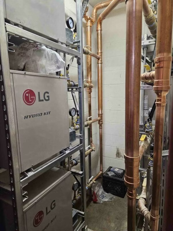
A hydro kit is an indoor unit that sits between the VRF refrigerant piping and the building’s water loop. Inside is a brazed plate heat exchanger that transfers thermal energy from the refrigerant to circulating water. The kit connects to the VRF outdoor unit exactly like any other indoor unit, and the system’s central controller manages it alongside wall-mounted heads, ducted units, and cassettes.
Individual hydro kit modules top out at roughly 8 to 10 tons of heating capacity depending on the manufacturer. LG’s mid-temperature chassis is offered in 3.5-ton and 9.5-ton nominal capacities, while Daikin’s VRV HT Hydrobox modules range from 14 to 22.4 kW.¹ ²
For larger buildings, water communication kits allow the VRF outdoor unit to interface with field-supplied, high-capacity plate heat exchangers, scaling VRF-to-hydronic capacity up to 32 tons by manifolding multiple modules in parallel.
Mid-Temp vs High-Temp: What the Cascade Buys You
The distinction between mid-temperature and high-temperature hydro kits comes down to one question: how hot does the water need to be?
Mid-temperature kits transfer heat directly from the primary VRF refrigerant (R-410A or R-32) to the water loop through a brazed plate exchanger. No secondary compressor, no secondary refrigerant circuit. Maximum leaving water temperature is typically 113°F to 122°F (45°C to 50°C), which works for radiant floor heating and DHW preheating but falls short for buildings with high-temperature radiators designed for 180°F boiler water.
High-temperature kits solve this with a cascade system. The primary VRF refrigerant rejects heat into a secondary refrigerant circuit (typically R-134a) housed inside the hydro kit. A dedicated inverter scroll compressor in that secondary circuit boosts discharge pressure to produce leaving water temperatures up to 176°F (80°C).¹ Standard R-410A or R-32 compressors cannot reach those discharge temperatures without destroying lubrication or tripping safety limiters, which is why the secondary circuit exists.

Efficiency drops as the thermodynamic lift increases. At 35°F outdoor, a high-temperature cascade system producing 140°F water typically delivers a combined COP of 3.0 to 3.6. At 17°F, expect 2.0 to 2.5. At 0°F, the system still runs (advanced VRF outdoor units with vapor injection maintain capacity down to -13°F), but COP falls to 1.6 to 1.9.³ These numbers reflect total system input, not just the cascade compressor. Some manufacturer datasheets quote internal cascade COPs of 4 or 5, which only account for the secondary compressor’s electrical input against heat already delivered by the primary circuit.
Heat Recovery: When Cooling Pays for Your Hot Water
In a heat recovery VRF system (3-pipe architecture), the branch circuit controller routes high-pressure discharge gas to zones calling for heat and low-pressure suction gas to zones calling for cooling. When a building simultaneously needs cooling in server rooms, kitchens, or south-facing offices while needing hot water elsewhere, the hydro kit captures that rejected heat instead of dumping it outdoors through the condenser.

This is where the economics shift. Published field data shows combined COPs as high as 8 in full heat recovery mode for simultaneous heating, cooling, and hot water operation, with seasonal efficiency improvements of 28% or more compared to non-heat-recovery VRF systems.⁴ A Department of Defense ESTCP demonstration documented a 57% reduction in primary energy use when a VRF system replaced a conventional VAV system, with waste heat routing handling a significant share of the building’s domestic hot water load.⁵
U.S. Census data shows heat pumps now account for 46% of heating systems in newly completed homes, trailing gas furnaces by a single percentage point.⁶ In 2024, heat pumps outsold gas furnaces nationally by a 30% margin. These numbers reflect new construction only, not the replacement market, but the trajectory is clear: the boiler-to-heat-pump conversation is happening now.
Three Installation Mistakes That Destroy Hydro Kits
Buffer tanks are not optional. Inverter compressors need minimum run times for oil return and EEV stabilization. Piping a hydro kit directly into a heavily zoned hydronic system (multiple thermostatic radiator valves opening and closing independently) causes aggressive short-cycling that leads to premature compressor failure. A buffer tank hydraulically decouples the heat source from the distribution system, ensuring steady flow across the plate exchanger and the thermal mass the compressor needs to run smoothly.

Glycol derating changes the math. VRF control boards calculate capacity assuming pure water. Adding propylene glycol for freeze protection reduces the fluid’s specific heat and increases viscosity. The derating can cut heat transfer efficiency by 3% to 10% depending on concentration. If the circulating pump is not upsized to overcome the additional pressure drop, the hydro kit trips on high-pressure or high-temperature safety limits. The glycol mix ratio must be factored into design calculations from the start, not figured out during commissioning.
Never bypass a flow switch. Brazed plate heat exchangers have microscopic internal clearances. If refrigerant evaporates inside the exchanger without adequate water flow absorbing the thermal energy, the water side freezes, the plates expand, and the exchanger ruptures. Factory flow switches prevent this. Bypassing a nuisance-tripping flow switch during a service call will physically destroy the hydro kit within minutes.
With the R-32 transition accelerating across VRF product lines and new A2L charge limit calculations affecting mechanical room sizing under ASHRAE 15-2022, hydro kit installations are getting more complex. But the fundamental value proposition remains: a properly installed hydro kit lets a VRF system replace the boiler without replacing the building’s existing hydronic infrastructure.
Additional Sources
- “VRV HT Hydrobox Design Guide”, Daikin Europe, Engineering Catalog, 2024.
- “Multi V Hydro Kit Product Data”, LG Electronics, Product Bulletin, 2024.
- “Ecodan E-Generation High Temperature Series”, Mitsubishi Electric, Product Data, 2023.
- “VRV 5 Heat Recovery Product Data”, Daikin Europe, Technical Literature, 2024.
- “Cold-Climate Demonstration of VRF Heat Pump Systems”, DoD ESTCP/GTI Energy, Case Study, 2019.
- “Characteristics of New Housing”, U.S. Census Bureau, Government Data, 2025.
Whether you require installation, repair, or maintenance, our technicians will assist you with top-quality service at any time of the day or night. Take comfort in knowing your indoor air quality is the best it can be with MOE heating & cooling services Ontario's solution for heating, air conditioning, and ventilation that’s cooler than the rest.
Contact us to schedule a visit. Our qualified team of technicians, are always ready to help you and guide you for heating and cooling issues. Weather you want to replace an old furnace or install a brand new air conditioner, we are here to help you. Our main office is at Kitchener but we can service most of Ontario's cities
Source link