
Key Takeaways
- Standard HVAC NTC thermistors read 10,000 ohms at 77°F (25°C): The resistance drops as temperature rises following a non-linear curve. Testing requires disconnecting the sensor from the control board first, because backfeed through parallel circuits on the PCB produces inaccurate readings.
- Pressure transducers output 0.5 to 4.5V DC, not 0 to 5V: The margins below 0.5V and above 4.5V are reserved for fault detection. A reading in those dead zones tells the board the sensor wire is severed or shorted, triggering an immediate system halt.
- The inverter board calculates superheat in real time to drive EEV position: It reads suction pressure, converts the voltage to saturation temperature using the refrigerant’s PT table, then subtracts that from the suction line thermistor reading. This calculation runs continuously, not on a timed interval.
- A drifted thermistor causes misdiagnosis because it triggers no error code: Unlike an open circuit (which throws a hard lockout), a thermistor that has shifted 10% to 15% out of calibration silently corrupts the board’s superheat calculation, causing the EEV to starve the evaporator while the actual refrigerant charge is correct.
Every inverter-driven HVAC system relies on two types of sensors to function: NTC thermistors that measure temperature and pressure transducers that measure refrigerant pressure.
The control board uses these inputs to calculate superheat, subcooling, and discharge temperature in real time, then modulates compressor speed, fan speed, and electronic expansion valve position based on the results. When a sensor drifts or fails, the board’s calculations go wrong, and a technician who does not understand what the board is seeing will chase a refrigerant problem that does not exist.
NTC Thermistors: What the Numbers Mean

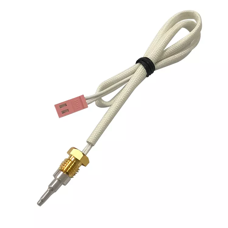
NTC stands for negative temperature coefficient. As temperature increases, the resistance of the thermistor decreases. The industry standard for HVAC applications is the 10kΩ thermistor, which outputs exactly 10,000 ohms at a baseline of 77°F (25°C). The Beta value (typically 3950K) determines how steeply the resistance changes across the temperature range.¹
The relationship between resistance and temperature is non-linear. At 32°F, resistance is roughly 32,650 ohms. At 120°F, it drops to approximately 3,760 ohms. The full curve follows the Steinhart-Hart equation, but in the field, a manufacturer resistance chart is the practical diagnostic tool.¹
| Temperature | Expected Resistance |
|---|---|
| 32°F (0°C) | ~32,650 Ω |
| 50°F (10°C) | ~19,900 Ω |
| 77°F (25°C) | 10,000 Ω |
| 100°F (37.8°C) | ~5,820 Ω |
| 120°F (48.9°C) | ~3,760 Ω |
Typical values for a 10kΩ Type 3 NTC thermistor. Exact figures vary by manufacturer and Beta value.
To test a thermistor accurately, disconnect the sensor harness from the control board before measuring. Testing while plugged in allows the multimeter’s signal to backfeed through parallel circuits on the PCB, producing wildly inaccurate readings. Measure resistance across the thermistor pins, then compare the result against the known ambient temperature of the sensor head (verified with a calibrated digital thermometer). Acceptable tolerance is ±1%, roughly ±0.5°F accuracy. If resistance deviates beyond 10%, the sensor has drifted and needs replacement.¹
PTC (positive temperature coefficient) thermistors work the opposite way: resistance increases with temperature. They serve as self-resetting fuses for motor overload protection and inrush current limiting, not for environmental temperature sensing.
Pressure Transducers: The 0.5 to 4.5V Signal
Pressure transducers in residential and light commercial inverter equipment use a ratiometric design powered by a 5V DC reference rail from the control board. The transducer’s piezoresistive strain gauge flexes with refrigerant pressure, outputting a voltage proportional to that pressure.² ³
The output range is 0.5V to 4.5V DC. Not 0 to 5V. This is one of the most commonly repeated errors in HVAC training materials. The margins below 0.5V and above 4.5V are intentionally reserved for out-of-bounds fault detection. If the board’s analog-to-digital converter reads below 0.5V, it interprets an open circuit (severed wire or lost ground). If it reads above 4.5V, it interprets a short-to-supply inside the sensor body. Either condition triggers an immediate system halt.²
Before condemning a pressure transducer, verify the 5V DC reference rail from the board to the transducer harness with a multimeter. If the board’s internal voltage regulator is failing and outputs 4.1V instead of 5.0V, the transducer’s entire ratiometric scale shifts downward. The board miscalculates saturation temperature even though the transducer itself is working correctly. Replacing the transducer changes nothing. The fault is on the board.
How the Board Calculates Superheat
The inverter board calculates superheat using two sensor inputs: the suction pressure transducer and the suction line thermistor. First, the ADC converts the transducer’s voltage to a pressure value. Then the board cross-references that pressure against the refrigerant’s pressure-temperature lookup table (stored in firmware) to determine saturation temperature. Finally, it subtracts the saturation temperature from the suction line temperature reported by the thermistor. The result is real-time superheat.⁴
This calculation drives the electronic expansion valve. EEVs use stepper motors with 500 to 2,000 steps of resolution, allowing the board to meter refrigerant with precision that mechanical TXVs cannot match. A TXV relies on a thermal sensing bulb whose response time is 30 to 90 seconds, producing superheat swings of ±3 to 5°F. An EEV responds in 5 to 15 seconds and holds superheat within ±1 to 2°F.⁴ ⁵ At partial load (as low as 5% of nominal capacity), the EEV continues metering accurately while a TXV would hunt or flood, which is why inverter compressors require electronic expansion to operate across their full speed range.
Inverter-technology air conditioners captured over 70% of global shipments in 2025, a share growing at roughly 7.5% annually.⁶ As that installed base expands, sensor diagnostics become a baseline field skill, not a specialty.
When Sensors Fail: Why Good Charge Looks Bad
Thermistor failures break into three categories. An open circuit (severed wire, cracked semiconductor) sends infinite resistance to the board, which reads a 0V logic drop at the ADC and triggers a hard lockout with an explicit error code. Connector corrosion from moisture ingress increases resistance at the plug, causing the board to read a lower temperature than actual. Both are identifiable.
The third mode is the dangerous one. Resistance drift occurs when the semiconductor material degrades through years of thermal cycling. The thermistor continues operating, the board receives a plausible signal, and no error code fires. But the reading is wrong.
Take this common misdiagnosis trap. A suction line thermistor that has drifted high (reading 12,000 ohms instead of 10,000 at 77°F) tells the board the line is colder than it actually is. The board calculates a lower superheat than actual, decides the evaporator is flooding, and closes the EEV to protect the compressor from liquid slugging. The evaporator starves, suction pressure drops, and the coil frosts over. A technician who does not check the sensor first will recover the charge, weigh in new refrigerant, and find the same frost pattern repeating within hours.
Field Measurements
Tip: Measure temperature with a calibrated contact thermometer at the sensor location. Disconnect the thermistor from the board before measuring resistance to avoid backfeed through parallel PCB circuits.
Superheat Comparison (Optional)
Sensor Analysis
Expected Resistance
—
enter temperature above
Board Sees
—
implied temp from resistance
Thermistor Deviation
—
measured vs expected
Transducer
—
0.5 to 4.5V range
Verdict
Enter Measurements Above
Fill in thermistor resistance, temperature, and transducer voltage to run the diagnostic.
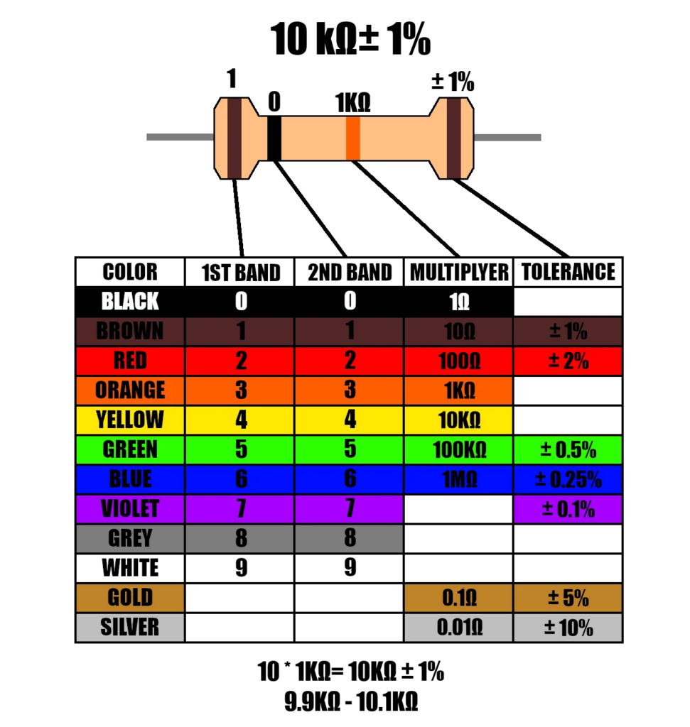
The fastest field diagnostic is a 10kΩ axial resistor. Disconnect the suspect thermistor and insert the fixed resistor directly into the board’s thermistor plug. This forces the microprocessor to read exactly 77°F (25°C). If the system immediately resumes normal operation or clears the fault, the problem is the thermistor, not the board and not the charge. A $2 resistor just eliminated the most expensive diagnostic dead end in inverter troubleshooting.
With A2L refrigerant sensors adding another layer of sensor inputs to inverter systems and tighter measurement accuracy demands from new refrigerant blends, the margin for sensor error is shrinking. Understanding what the board sees is now as important as understanding what the gauges show.
Additional Sources
- “NTC 10K Type 3 Temperature Table”, Johnson Controls, Engineering Reference, 2024.
- “SPKT-P Series Ratiometric Pressure Sensors”, Carel, Product Data, 2024.
- “AKS 32R / AKS 2050 Pressure Transmitters”, Danfoss, Product Data, 2024.
- “Electronic Expansion Valves”, HVAC Systems Encyclopedia, Technical Reference, 2024.
- “EEV vs. TXV: Which Expansion Valve Is Better?”, Square HVAC, Technical Comparison, 2026.
- “Air Conditioner Market Size and Growth”, Mordor Intelligence, Market Research, 2025.
Whether you require installation, repair, or maintenance, our technicians will assist you with top-quality service at any time of the day or night. Take comfort in knowing your indoor air quality is the best it can be with MOE heating & cooling services Ontario's solution for heating, air conditioning, and ventilation that’s cooler than the rest.
Contact us to schedule a visit. Our qualified team of technicians, are always ready to help you and guide you for heating and cooling issues. Weather you want to replace an old furnace or install a brand new air conditioner, we are here to help you. Our main office is at Kitchener but we can service most of Ontario's cities
Source link