
There is a very nuanced and misunderstood situation which plagues a lot of AHUs. It occurs in AHUs which utilize airflow tracking for control of its return fan and either intentionally, or unintentionally, operate in a fully recirculating configuration. This is the fourth of several articles in a series written with the intent to explain the issue. The series provides several case studies for how I have seen the situation manifested and how a unique solution in each case was needed to rectify the issue.
The AHU recirculating mode death spiral occurs when the outdoor and relief air dampers are fully closed, the return damper fully open, and the return fan is attempting to control to a return airflow setpoint. That setpoint is reset to maintain an offset from measured supply airflow. With the AHU in a fully recirculating damper configuration, that return airflow setpoint will never be tracked on stably. The supply and return fans will begin to fight each other, and eventually it results with one fan at full speed, the other at minimum speed, and various other second order effects impacting operations of the system. Refer to Part I for a more detailed explanation of the death spiral.
There are often scenarios where an AHU is intentionally put into such a fully recirculating configuration. Case Study 1 in Part I of this series described such a situation. There are also times when AHUs unintentionally find themselves in a damper configuration that allows the AHU recirculating mode death spiral to begin. Case Studies 2 and 3 provided examples of this. Case Study 4 below provides another example, but with a slight twist. This AHU doesn’t control its return fan with the conventional airflow tracking approach discussed in Parts I through III, airflow tracking occurs at the served spaces, with return VAV boxes controlling return airflow while the return fan just maintains adequate return air static pressure to allow those boxes to operate properly.
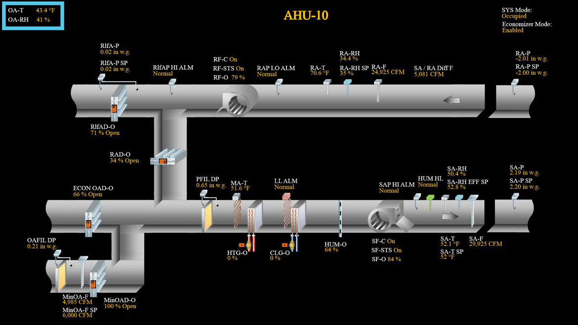
FIGURE 1: Typical operating conditions with economizer enabled. (Courtesy of Hawke Institute for Facility Systems)
Case Study 4: Control Approach:
The AHU in question was being functionally tested after initial installation in a new hospital. This was the same hospital discussed in Part III, and the AHU sequence of operation was quite similar with the only difference being the return fan control.
This AHU actively controlled a minimum outdoor air damper (MinOAD-O in Figure 1) to ensure minimum ventilation requirements were being met. It did so by measuring the outdoor airflow by use of a duct mounted airflow measuring station (MinOA-F).
The return fan controlled to maintain return air static pressure (RA-P) at setpoint (RA-P SP). Return air VAVs located in the operating rooms served by this AHU modulated to maintain their airflow setpoint. Therefore, the overall return airflow was collectively controlled for by the return air VAV boxes. The return airflow measuring station (RA-F) at the AHU was a monitoring only sensor, not used for control.
The relief air damper modulated to maintain relief air pressure (RlfA-P) at setpoint (RlfA-P SP) to ensure air was never brought in backwards through the relief air duct.
The return air damper (RAD-O) and economizer outdoor air damper (ECON OAD-O) modulated inverse of each other based off the economizer control loop.
The AHU was tested in March, with relatively cool ambient conditions. The AHU had been operating with the economizer enabled in the weeks leading up to functional testing without issue. Figure 1 represents typical operation of the AHU during cool ambient conditions and the economizer enabled. Note that with the economizer outdoor air damper open at 66%, the measured minimum outdoor airflow (MinOA-F) was under setpoint, but that was due to the location of that airflow measuring station. More than sufficient outdoor air was being brought in collectively through the two outdoor air paths.
As part of the testing, the economizer was then disabled. Figure 2 is what the AHU should theoretically look like with the economizer disabled and operating in a minimum outdoor airflow configuration. Outdoor air (MinOA-F) is greater than the difference between supply airflow and return airflow (SA / RA Diff F), therefore the relief damper should be slightly open to relief the excess return air being brought back from the space. But just like the AHU is Case Study 3 last month, the configuration depicted in Figure 2 is not what happened, below is what actually occurred.

FIGURE 2: Expected operation with economizer disabled. (Courtesy of Hawke Institute for Facility Systems)
Initial testing:
The temperature controls contractor had warned me this unit would trip out once we disabled the economizer, he had pretested it the day before. I wanted to see it anyways so we could be certain in our forthcoming recommendations to the design engineer. So, we pulled up the BAS programming tool to watch the inputs and outputs in real time. We then disabled the economizer.
A couple minutes after disabling the economizer, the unit tripped on the return air static safety switch. This is a different type of second effect than what we saw in the Case Study 3 AHU, but at this point in the functional testing process we kind of knew it had to be another manifestation of the AHU recirculating mode death spiral.
When the economizer first disabled, the AHU initially went to a state depicted in Figure 3. The return air damper went fully open, and the economizer outdoor air damper went fully closed. The relief air damper immediately closed. This was not expected, but certainly possible since there are many factors which impact the relief plenum pressure (e.g. building pressure, ambient wind direction and velocity, return damper resistance to flow).
The outdoor airflow reading (MinOA-F) was reading higher than its setpoint (MinOA-F SP), and so the minimum outdoor air damper (MinOAD-O) started to close. This forced the supply fan to start pulling more airflow through the return air path. This meant an increase in airflow started to be sucked through the return air VAV boxes, those boxes’ airflow sensors detected that and the boxes responded by closing their dampers more in an effort to track on their respective airflow setpoint. With added restriction at the closing return VAV box dampers, return air pressure dropped quickly and the return fan slowed down accordingly. This forced the supply fan to suck more air through the minimum outdoor air duct, which forces that damper to close even more. Eventually, as the minimum outdoor air damper closes more and more, the return fan ends at minimum speed. The supply fan was big enough to keep sucking excess flow through the free spinning return fan. Since the return fan bottomed out on minimum speed, the return VAV box dampers had to close even more. The return duct static pressure dropped so quickly that the return air static safety switch triggered, disabling the unit entirely. Figure 4 depicts the configuration of the AHU the moment just prior to the return air static safety switch triggering.

FIGURE 3: Initial configuration after economizer disabled during testing. (Courtesy of Hawke Institute for Facility Systems)
The Fix:
The solution to fix this was already in the works, since it had been worked through on the previous AHUs that had airflow tracking for the return air fans (see Case Study 3 in Part III of this series). The solution is listed again below as a reminder.
We needed a solution more resilient to an unexpected closing of the relief air damper and uncoordinated airflow readings from the many airflow measuring stations at play. This AHU was also susceptible to future balancing efforts. For example, if the operating rooms served by this AHU were being recertified by a TAB technician sometime in the future, it is likely they will be modifying the airflow setpoint utilized by the return air VAVs in an effort to dial in space pressures. Should drastic adjustments be made, it is possible the collective difference between supply VAV boxes’ setpoints and return VAV boxes’ setpoints, could exceed the minimum outdoor airflow setpoint (MinOA-F SP). Such a situation would force the AHU into the recirculating mode death spiral even if all the airflow measuring stations in the building were reading perfectly.
The following was proposed to the design engineer, accepted and proved to be viable.
- Modify minimum outdoor air control loop to modulate MinOAD and then the RAD in sequence. See Figure 5.
- This will allow the recirculated air path (i.e. the RAD) to become more restrictive if needed, which will increase MinOA-F should it be tracking below MinOA-F SP with MinOAD fully open. Note: this was not the situation described above, but could easily be witnessed in the future.
- Place an adjustable low limit for the MinOAD command (e.g. 75%) and RAD command (e.g. 60%).
- The minimum position placed on the MinOAD is there to prevent the outdoor air damper closing too far should MinOA-F consistently read higher than MinOA-F SP.
- This will prevent the AHU from approaching a fully recirculating configuration, which will lead to the AHU recirculating mode death spiral.
- The minimum position placed on the RAD is there to ensure RAD doesn’t go too far closed should the minimum outdoor airflow setpoint (MinOA-F SP) prove to be impossible to satisfy.
- This will prevent a situation where all the supply air is pulled through the minimum outdoor air duct. This could overextend a coil and impact supply air temperature control.
- The minimum position placed on the MinOAD is there to prevent the outdoor air damper closing too far should MinOA-F consistently read higher than MinOA-F SP.
- The command signal that goes to the RAD will be the lesser (i.e. more closed) command between the minimum outdoor airflow control loop, and the economizer control loop.

FIGURE 4: Configuration several minutes after economizer disabled during testing, just prior to RAP LO ALARM triggering. (Courtesy of Hawke Institute for Facility Systems)
Conclusion:
This fourth case study demonstrated another example of how the AHU recirculating mode death spiral can manifest itself even when the AHU was not intended to be in a fully recirculating configuration. This one was a little different though, the presence of return air VAV boxes leads the AHU recirculating mode death spiral to result in return air static pressure safety trips. This is a much more dangerous situation. Should such a switch not trigger as intended, return ductwork could have collapsed.
This was the result of an AHU sequence of operation that initially did not have guardrails (i.e. the Min OAD Low Limit in Figure 5) in place to protect the system from putting itself into a fully recirculating configuration when the various airflow measuring stations drifted and became uncoordinated with each other.
I’ve got more case studies for you. It seems few AHU sequences of operation can escape the AHU recirculating mode death spiral from rearing its head, and a customized solution to improve the robustness of the sequence is needed each time. Next month looks at an altogether different AHU sequence of operation, from a different hospital, which too fell victim.

FIGURE 5: Modifications to minimum outdoor airflow control loop sequencing. (Courtesy of Hawke Institute for Facility Systems)
Captions:
Figure 1: Typical operating conditions with economizer enabled. (Courtesy of Hawke Institute for Facility Systems)
Figure 2: Expected operation with economizer disabled. (Courtesy of Hawke Institute for Facility Systems)
Figure 3: Initial configuration after economizer disabled during testing. (Courtesy of Hawke Institute for Facility Systems)
Figure 4: Configuration several minutes after economizer disabled during testing, just prior to RAP LO ALARM triggering. (Courtesy of Hawke Institute for Facility Systems)
Whether you require installation, repair, or maintenance, our technicians will assist you with top-quality service at any time of the day or night. Take comfort in knowing your indoor air quality is the best it can be with MOE heating & cooling services Ontario's solution for heating, air conditioning, and ventilation that’s cooler than the rest.
Contact us to schedule a visit. Our qualified team of technicians, are always ready to help you and guide you for heating and cooling issues. Weather you want to replace an old furnace or install a brand new air conditioner, we are here to help you. Our main office is at Kitchener but we can service most of Ontario's cities
Source link